The Concept
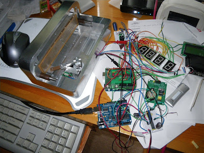
7-segment LED's form the digital readout (DRO). These are located on a moving sled that can move back and forth using a DC closed-loop motor control system. In front of the DRO is an array of lenses that allow for defocusing of the digits as they are shifted by the motor. This creates an unusual effect that can be implemented as desired in the programing. At this time the effect is randomized over the course of a single minute. The electronics clock is a real-time clock w/ battery so that when power is lost the time is retained. The overall controller makes use of a Dorkboard which is a version of the Arduino microcontroller. 2 buttons allow for changing minutes and hours and another 2 accessory buttons are used to disable the movement and to allow for triggering a 'night mode' that quiets the system in the evening. Everything is housed is a very sturdy, custom machined aluminum housing. A 32v DC power supply powers the system.
The Electronics
A complete schematic may be found here:
A Dorkboard was used as the microcontroller. This is an Arduino system based on the Atmel ATmega128 microcontroller.
The real time clock made use of a DS1307 board with battery backup. It communicates with the Arduino using an I2C interface. A MAX7219 LED driver IC was used to multiplex the LED digits. It communicates with the Arduino using a serial interface. The L298N dual full-bridge driver IC was used to drive the DC motor using a source voltage of 32v. The 32v supply fed into a LM2574 buck regulator IC to provide a 5v supply. A series of NOR gates are used to create 4 S-R latches that act as memory for button presses. The outputs of these latches feed into the Arduino as well as a series of OR gates to provide a single output for indication if a button has been pressed.
Here is an early breadboard of the LED setup w/ switches and the DS1307 real-time clock board:
Early testing of the drive system with breadboard:
Breadboard of the 32 to 5v power regulator circuit:
The final board, almost done:
The back side of the main board almost done:
I later switched from the L293D motor driver to the L298N as seen here. It is a much more bomber driver. I had been burning up many L293D's - I think because with my 32v supply I was operating close to the power dissipation limit. At this late stage, I only had room for the device on the back side of the board:
The inside of the clock w/ electronics and motor:
Inside the completed clock:
The Firmware
The code uses nearly all of the available memory of the ATmega128. Code is fully commented and may be found here:
Closed loop motor control is enabled by using Timer2 to generate the desired pwm to the motor. A PD controller algorithm was used. Encoder feedback is counted by setting up Timer1 as a hardware counter. These counts happen in the background and thus an interrupt is not necessary. With these timers taken, I was forced to use discrete IC's (S-R latches via NOR gates) as memory for any button presses since there were no interrupts available to capture the input.
The LedControl library was used for controlling the LED's.
The Mechanical Hardware
The drive system makes use of a 40:1 gear reduction off of a small DC motor. A DC motor was used to attempt to minimize noise in the system. Regular servos and steppers are LOUD. A linkage system drives a sled that rides on 2 sets of rods and bushings. The DC motor includes an optical encoder wheel w/ encoder which allows for closed-loop control of the drive system. Ball bearings form the user interface to the top two accessory switches and machined aluminum caps were used on the buttons for the rear time changing switches.
Here you can see the ball bearing switches:
There are 2 lenses per digit. The outer dome-shaped lenses were used for aesthetics but they also serve to magnify the digits. The inner, non-visible lenses are FOFP's or fiber optic faceplates. An FOFP is comprised of an optical mosaic of glass fibers which are fused together to form a cylindrical plate. The plate is effectively equivalent to a zero-thickness window since the image formed on one surface is precisely transmitted to the opposite surface with no change in focus and minimal loss of light. This device was used to induce an interesting defocusing effect. When the LED display is in contact with the FOFP, the image is transmitted sharply in focus. However when the display is moved away, a defocused image appears.
Here's an example of an FOFP:
The entire clock was designed and modeled in 3D CAD.
Almost all internal and external parts were custom machined from either aluminum or Delrin (drive parts). The gearing system and motor were obtained from an old optical scanner. The exterior parts were made with a combination of manual milling on a large Bridgeport and CNC milling on a Taig mill. The outer front housing was countour milled using the Taig mill with a Mach3 driven control system. The tool paths were generated using Pro/Engineer.
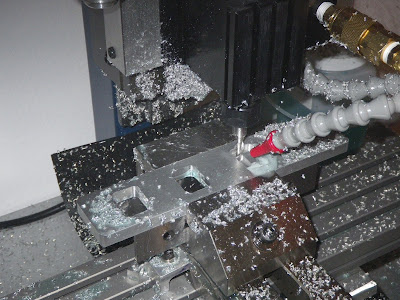
Here are some pics of the CNC process using the Taig milling machine.
The LED sled is being cut here:
Rough cut of the front faceplate:
Rough contouring on the faceplate:
Detail of the final contour pass on the faceplate:
The finished result of the faceplate (prior to adding the lens holes):
A lot of sanding and polishing was required to turn the relatively rough surfacing into the final smooth part.


